All posts by admin

QDrive troubleshooting guide: Error code E02

Technical Director Quin SystemsA call-out last week, to investigate an intermittent alarm on a flow wrapping machine with a Quin QDrive synchronising the lug belt with the film, has prompted me to write a troubleshooting guide. In this first post I tackle the action to be taken in response to error code E02 but if you have come across different occurrences of this alarm in complex installations and have devised your own solutions which may be of help to others, we’d love to hear from you.

What is error code E02?

E02 signifies that a motor or encoder timeout error has occurred. The controller is giving a command to the motor to move but it hasn’t gone anywhere or the encoder hasn’t sent the correct signal back. The timeout parameter says that if it hasn’t moved within a certain time then an error has occurred.

What action should be taken?

The motor may not be moving when instructed or the encoder may not be working and giving the feedback that the motor isn’t moving. After you have checked that the motor is actually working then you could try the following checks:
1. Is the encoder or resolver faulty, incorrectly wired or is there a problem with the cable?
2. Is the motor being physically stopped from moving, eg is there some mechanical reason why it isn’t moving? If the motor has a brake there may be a problem with the brake.
3. Check the parameters are correctly set up – more on this later.
4. The drive may not be seeing the encoder properly; there is a fault with the drive.

If it is a new installation and the motor isn’t moving as it should, then it could be a problem with the parameters that are being programmed into the drive. For example if the current loop setpoint, controlled by G6P1 is not set to zero then error code E02 will occur. Other parameters, listed in the table below, will result in an error code E02 if incorrectly programmed; these are the speed loop setpoint, nominal current, maximum current, maximum speed and shift angle.

Possible fault Parameter   Setting
Current loop setpoint incorrect. G6P1<>0 G6P1 Should be set to 0
Speed loop setpoint incorrect. G7P1<>2 G7P1 Should be set to 2
Nominal current too low G4P4=0 G4P4 Must be greater than 0
Maximum current too low. G4P5=0 G4P5 Must be greater than 0
Maximum speed too low. G4P6=0 G4P6 Must be greater than 0
Shift angle incorrect. G5P2 G5P2
Feedback cable incorrectly wired
Motor brake engaged


You could also check the ‘move word’ parameter. In the installation that I visited last week the ‘move word’ parameter was set to stop the motor going backwards as this could potentially break the lugs on the belt, however it was mapped (synchronised) to the film. When I analysed the motion with PTS scope, you could see that the film around the product moved backwards slightly as the belt came to rest. The lug belt was trying to follow the backwards movement but was constrained by the control system. It was in effect being told to go backwards which it couldn’t do resulting in timeout error, E02. The solution to increase the timeout (TO) and the error window (SE) so the set-up was less sensitive to minor movements and the alarm was not triggered.

Case study

The machine I visited was flow wrapping sausages. The QDrive was synchronising the lug belt so that the sausages are in the correct position for wrapping and are fully sealed. An intermittent error code E02 was occurring which was affecting productivity as the machine had been programmed to stop and reinitialise when this occurred. The cause and subsequent solution was as described in 3 above. The lug belt was trying to follow the backwards movement of the film as the product came to rest but was constrained by the control system. Because of this the position error on the lug belt increased as the film moved backwards and sometimes this triggered the position error. By increasing the position error window (SE) it was possible to stop the position error but sometimes there was a timeout error because the lug belt was not moving as the film moved backwards.
The solution was to adjust the position error window (SE) and timeout (TO) of so that both position errors and timeout errors were avoided during operator stops. The line was then run to test these modifications. The program was then modified once these parameters were confirmed.
On a different line, we observed an error code E02 once when the machine was stopped – it happened when the film was tightened by hand causing the master encoder to move backwards.

Future posts?

If there’s a subject that you’d like me to cover in future posts or you would like to share your experiences in a post please let me know; we’d love to hear from you.

John Lambe, Technical Director

Stainless steel linear guides from LinMot

Machine builders are increasingly demanding machines with higher hygienic standards to withstand aggressive liquids and foam cleaners.

To complement the introduction of the stainless steel motor to the LinMot product range, the matching guide is now available. Together with the stainless steel motors with high protection class IP69K, this complete system is suitable for direct use even under difficult ambient conditions. The stainless steel system is designed optimally to handle the use of aggressive liquids and foam cleaners, which are common in the pharmaceutical or food industry.

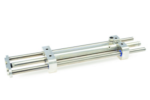
Stainless steel linear guides for use with stainless steel linear motors to withstand aggressive liquids and foam cleanersThe guide consists of two guide blocks, two guide shafts, and a load-mounting plate, all made from rustproof steel (mat. no. 1.4404, AISI 316 L). The precise linear motion is provided by hardened shafts supported in plastic sliding bearings. The bearing material is specially designed for use in food products and medical applications and is certified to FDA standards.

The design is characterized by its conveniently rounded surfaces, which make it easier to clean. A channel in the guide blocks also makes the slider completely flushable. The guide has a maximum stroke length of 510 mm. Together with the stainless steel motors, motions with an acceleration of up to 440 m/s² can be achieved.

  • Made of stainless steel (1.4404 / AISI 316)
  • Hardened stainless steel guide shafts
  • Sliding bearing with FDA approval
  • No seals; connections are welded
  • Tapered surfaces
  • Motor inside is completely flushable

The H-37 stainless steel guides and H-48 stainless steel guides are now available and more information is available on the LinMot website or by calling us to discuss your application.

Get in touch

Linear motors enable greater flexibility for robot grippers

With a robot that can handle tennis balls, tissue packs and champagne glasses, what more do we need for Wimbledon (apart from weather)?

Robot gripper developed with linear motors, is universally deployable and can safely and gently pick up even sensitive products and group them prior to setting them down.
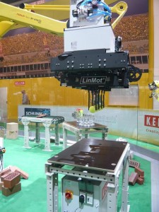
The new robot gripper arm from Keller HCW eliminates pneumatics with the use of linear motors, so reducing operating costs and protecting the environment. (Image source: Keller HCW)

By changing from pneumatic cylinders to linear motors, German machine builder Keller HCW has developed a universally deployable robot gripper with a high payload rating that can safely pick up hollow bricks, glasses, cat food packages, tiles, tissue packs and tennis balls with just the right amount of force. Benefits included improvements in precision, repeatability, maintenance and energy efficiency in addition to negating the need for multiple grippers and lost changeover time.

Keller HCW, who is one of the world’s leading manufacturers of machinery and plant for the heavy clay industry, also develops customised robotic solutions with over 500 robot installations. Robot grippers from Keller HCW (mainly pneumatic drives) have proven themselves for years in brickyards and other heavy ceramics operations. However, there were significant disadvantages of using pneumatic cylinders when different shapes and formats of bricks are run on the same line so alternative designs were investigated.

For example, they are used to grip unfired bricks (blanks) and to place them with a certain spacing that guarantees an optimal drying and firing process. The bricks are fed to the gripper on a continuously running transport belt in the form of a consolidated stack consisting of about 20 to 30 blanks. The gripper picks up the entire stack, spaces the individual bricks optimally while the robot is moving, and then places them as a group on special carriers or transport belts.

“The challenge here is that the strength of the blanks can vary, and therefore we can only apply a limited gripping force at a limited approach speed. There is also a limited time window available during which the bricks have to be picked up from the feeder belt as it continues to move,” explains Reinhold Ungruhe, the manager of Automation and Electrical Engineering at Keller HCW GmbH.

Up to now, the robot grippers that have been used for singulating bricks, as well as other handling process in the heavy ceramics industry, have mainly used pneumatic drives.

Stroke adjustments were previously limited to 10 mm by the pneumatics

Due to the limited stroke and the relatively slow speed of the pneumatic cylinders, the stroke adjustments had to be no greater than 10 mm. This is disadvantageous if different shapes and formats of bricks are run on the same line, which is increasingly the case.
In developed industrial countries today, it is typical that the few thousand bricks required for the roof of a house, including the special bricks (such as gable and ridge tiles), are produced for a specific customer in one batch on the same line.
In practice, this has meant that the brickyards have had to procure several grippers for each robot—typically 6-axis robots—and use them alternately in order to cover all of the formats and styles. With procurement costs of about 50,000 Euro per gripper, this can tie up a great deal of the company’s capital. An alternative possibility for the user is to procure just one gripper per robot and then to reconfigure it whenever a format or style change requires it. In order to minimize this time-consuming setup process for the user, Keller has come up with a hybrid gripper design. The pneumatically powered grippers can be adjusted by means of a rotary servo drive in order to be able to group more brick formats and styles using the same gripper.

Pneumatic adjustments require manual finesse

“In practice, however, it is very difficult to adjust the pneumatics,” says Reinhold Ungruhe. “Just the fact that the pneumatic actuators behave differently depending on the ambient temperature, and therefore the precise adjustment of the gripping point and the grip force is only partially possible.”

The condensate water and other contaminants in the compressed air are another factor. Pneumatic cylinders are also not maintenance-free. They need to be oiled, for example. Seals harden or leak, especially when the drive works at a high frequency, so that the entire cylinder needs to be replaced.
Keller therefore took a step further and developed a completely electrically powered demonstration gripper that does not have these disadvantages. Twelve linear motors, model PS01-37Sx120-HP-N from LinMot*, move the gripper jaws that are mounted directly on them. They have a maximum stroke of 120 mm, a maximum force of 122 N, and an especially compact form factor.

High dynamics and repeatability with linear motors

“Linear motors can be controlled more precisely and are more dynamically than pneumatic drives. They can also cover a much longer stroke in a short time,” says the Keller specialist for automation and electrical engineering, summarizing the advantages.

The pattern in which the bricks are placed can be entered at the system’s user interface and changed at the push of a button. No time-consuming gripper change or setup is required. Unlike with pneumatic drives, the grip force can also be controlled directly. This ability and the long stroke, combined with high dynamics, are what make this gripper so universally deployable and why it can handle sensitive products, such as glasses or cardboard packages, as safely as robust products.
The linear motors in the new gripper are actuated by 12 ProfiNet servo controllers from LinMot’s C1100 series. These have been specially designed for applications where pneumatic cylinders are replaced by linear motors. The controllers are very compact and lightweight, with a height of 146 mm, width of 26.6 mm, and depth of 106 mm.

“This is important for the payload capacity of the gripper, because we wanted to mount the controller directly on the gripper, in order to keep to a minimum the number of cables running along the robot,” explains Reinhold Ungruhe.

The disadvantage of the additional weight, however, is typically more than made up for by eliminating valve banks, mechanical components, and sensors that used to be required, as well as by the greater flexibility and repeatability of the electric drives.

“For this series, it would also make sense to use LinMot multi-axis modules or distributed motors with integrated drive electronics to further reduce the weight and space required,” adds the automation expert.

Environmentally friendly and economical

In developed countries, users also focus on another consideration of the direct electric drives: their frugal use of energy.

“More and more manufacturers of heavy ceramics products are discovering energy efficiency in their production facilities as a differentiator and image factor that drives sales,” reports Reinhold Ungruhe.

Compressed air does not fit this image, because after all it is one of the least efficient and therefore most expensive energy media. Only about 5% of the energy applied is available as useful power at the actuator. For fast cylinders, in particular, the high noise level is an indication that a lot of energy quite literally disappears into thin air. The higher procurement costs for an electric drive are quickly paid back. Even using conservative figures, its efficiency of about 97% means that it amortizes within a maximum of three years.
No wonder, then, that more and more companies are attempting to eliminate compressed air entirely in their production facilities. Keller recently built a system for packing hollow concrete blocks with rock wool with no pneumatics at all.

“The great interest that this gripper drew at the Automatica in Munich confirms our assessment that many other industries beyond the field of heavy ceramics will also follow this trend, and are looking for flexible, reliable gripping and singulating solutions based on linear motors,” says Reinhold Ungruhe, optimistically looking to the near future.

This post is taken from an article written by Franz Joachim Rossmann, technical journalist, Gauting.

The Closing Twist

The use of linear – rotary motors in closure lines to enable frequent product changeovers

Capping processes can be designed much more flexibly with linear-rotary motors than with conventional cam disc technology. Tölke, a packaging machinery specialist, has outfitted a new high-performance filling and closing line for a well-known pharmaceutical company with linear-rotary motors from LinMot. The resulting benefits included shorter setup times, lower downtime, and a wider range of applications for the machine.

Linear rotary motor in capping machine
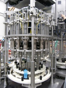
By using the linear-rotary motor from LinMot, Tölke was able to decouple the closing process from the motion of the turntable. This allows a closing station to be swapped out much faster in case of damage, thus minimizing downtime. (Photo: Rossmann)

Tölke specialises in machinery for bottle closing and capping machines and provides complete lines for sorting, aligning, filling and capping for well-known manufacturers in the beverage and cosmetics industries. These cappers have an output up to 500 bottles per minute with a packaging cycle for each bottle of only 0.12 seconds however when Tölke was commissioned for a high performance filling and capping line for an application that required frequent product changeovers a more flexible solution was required.

A limitation of conventional cam-stroke technology, as utilised in traditional capping machines, is that, if the closing process itself needs to be modified for a product changeover, it is usually necessary to change out the mechanical cams involved in the linear motion of the screwing process. This is a time-consuming and costly process and modern production lines require quick product changeovers. As a consequence a carousel machine was developed with 16 closing stations. The entire screwing process is handled by one linear-rotary motor (model PR01-84) at each station.

This electric motor, part of the PR01 series from LinMot, was specially developed for the closing and screwing process. It combines both a linear motor and a rotary direct drive in a compact housing, each of which is controlled separately. This means that any combination of linear and rotary motions can be implemented.

“For the rotary part of the screwing process, we have been using a rotary servomotor instead of a pneumatic motor for a long time wherever the screwing application requires a defined turn angle and a defined torque, and when we want to perform a product changeover at the push of a button,” explains Franz-Josef Patzelt, one of the managing directors of Franz Tölke GmbH.

What is new, however, is the use of an electronic linear axis in the closer.

“The cap needs to be picked up, placed on the bottle, and then guided so as to provide optimal support for the rotary motion,” says Markus Kröger, the Tölke project manager responsible for this job. “If this linear motion were controlled by a cam disc, then the heights at which the cap is picked up and placed down would be fixed, and the entire motion sequence would be defined.”

Filling and capping machine
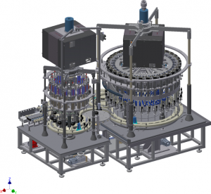
Flexible filling and closing machine from Tölke for output capacity of up to 300 bottles/min and a filling volumes of up to 250 ml. (Photo: Tölke)

If modifications to the motion sequence were required for a product changeover, then the mechanical solution would require different closure heads or even different cam discs to be installed, or the machine builder would have to integrate adjustable cam discs. In some cases, a spring would also need to be installed to compensate for the weight of the head.

“With a direct drive and an electronic stroke curve, none of this is needed anymore,” explains Markus Kröger. With the right parameter sets for the programmed motion sequence, or by invoking a predefined recipe, the motion of the linear motor can be designed as needed and optimally adapted to the individual requirements of the application.”

This means that different types of closures, including screw-on and press-on caps, can be processed on the same machine. Even different press forces or thread pitches, such as are found on containers with and without safety caps, can be handled by a linear drive without any mechanical reconfiguration.
In addition, a linear-rotary motor like the PR01, with its two independently controlled axes, can start the rotary motion during the linear stroke, decoupled from the position of the turntable. The machine builder therefore has more freedom when designing the machine, allowing the cycle time to be shortened.

Other advantages include modularisation of the machine, simple changeover of the screwing station and the ability to analyse the data produced by the drive (torque, speed, angle, vertical position, speed and force) to improve performance.

“We can use the data provided by the drive to determine the number of revolutions actually performed, so that a separate check of the height of the closed container in order to monitor the screwing process can also be eliminated,” adds Franz-Josef Patzelt, citing a practical example.

Tölke have considerable expertise in this area and had developed a solution prior to the use of the PR01 linear-rotary motor, wherein the linear motion was generated by a servomotor in conjunction with a ballscrew spindle. The ballscrew, however, had to be protected against dust, which requires additional design effort that is not necessary for the fully assembled linear-rotary motor.

“The linear-rotary motor from LinMot is much simpler to use, as an integrated unit, and takes up less space,” says Markus Kröger. “The PR01 is thus the ideal solution for lines like our high-performance closing machines, where the rotary screwing process must be as flexible and efficient as possible.”

To find out more about linear-rotary motors take a look at our web site or alternatively we would love to hear from you.


Weetabix enhances its Alpen production line by upgrading obsolete servo drives

Cost effective solution for upgrading outdated servo drives without affecting production.For decades, Weetabix Food Company has been at the forefront of food manufacturing innovation. Its popular Alpen bar range is one such example, accommodating a new generation of breakfast eaters looking for a nutritious treat that is quicker and more convenient to consume. But while this particular breakfast innovation has made our mornings more efficient, outdated drive technology was impacting efficiencies at Weetabix’s Alpen Factory, forcing the team to look towards new innovations.

The Alpen Bar production line operates round the clock; at the end of the line, where wrapped bars are collated and flow wrapped. 25% of capacity is handled with a Bosch HSM wrapping machine (formerly SIG). Critical to the operation of this machine were IRT 1300 servo drives, but due to their discontinuation, replacement parts were becoming difficult to source. Karl Wigley, Reliability Engineer at Weetabix Food Company, was charged with addressing this issue and finding a cost effective solution, one that could be implemented with minimum downtime and risk.

“Our original wrapping machine was fitted with fourteen IRT 1300 servo drives which were located in two cabinets,” commented Karl. “The flow wrapper still met our requirements and the IRT servo drives – critical to the operation of the machine – were running smoothly. Unfortunately, the IRT drives had been superseded by a new generation of drives, the 2000 series, meaning replacement parts were no longer being manufactured. Ultimately, we were faced with the decision to replace our servo drives.”

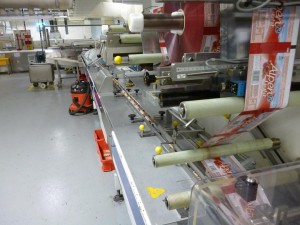
HSM flow wrapper fitted with IRT 1300 servo drives requiring upgrade to extend machine lifeWeetabix systematically implements reliability centred maintenance (RCM) and condition based monitoring (CBM) to increase machine uptime, increase cost effectiveness of capital investments and improve decision making – an essential part of its production process. Weighing the immediate financial benefits of renovating existing technology with the longer term benefits of deploying a more contemporary design with increased efficiency and performance, Karl and the Weetabix team made the decision to entirely upgrade their servo drives.

Having made the decision to enhance its production line, Weetabix approached Quin Systems, a distributor and technical support organisation in the UK and Ireland for Swiss-based IRT SA to take its existing 1300 drives and upgrade to the 2000 series. Fearing a drop in production during the installation process, in the first stage, the two companies worked together to agree a work plan that minimised risk and inconvenience. The solution was found in upgrading the cabinets on separate dates and on weekend so that normal practice could resume and without causing any financial loss.

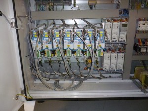
Photo of cabinet with upgraded servo drives, reusing existing motors, command cables, encoders ans control system.For maximum efficiency, Quin fitted the new IRT drives in place of the existing drives in the same cabinet space and reused the existing motors, encoders, command cables and control system, which delivered the most cost effective solution attainable.

“Quin Systems carried out the installation, commissioning and testing of our new drives to the highest possible standard and offering a quality of service that is rarely found these days,” Karl commented.

“Despite a few minor hiccups, the machine was up and running by the scheduled time and little to no production time was lost. The Quin engineer was present at the start of production on Sunday night and returned in daylight hours to give advice and support to our team as was required. We couldn’t have asked for a smoother transition.”

Karl reports that the flow wrapping machine is now handling better than ever before. Increased responsiveness means the machine takes less time to reach the optimum speed. Hunting (where the system first overcorrects in one direction and then the opposite direction) is reduced, resulting in smoother handling and lower energy consumption. More significantly, Weetabix has implemented a cost effective solution on this very important production line which will extend the machine life, improve reliability and save production down-time.

“It’s proved a great decision to replace our drives and we’ve been left very satisfied,” concluded Karl. “The Alpen Bars Factory is now one of the prime examples of production line innovation at Weetabix and we’re looking forward to producing bars for UK consumers over the coming years.”

Please contact us or take a look at our website to learn more about our IRT drive upgrade service.